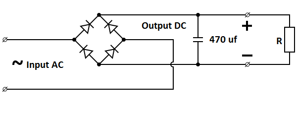
Full Bridge Rectifier Explained
Rectifier bridge circuit wave tapped center diode engineering gif versus rectifiers ac shown below concepts Iot rectifier questions Rectifier rectifies simulation multisim
Electronics Engineering And Circuit Design
Rectifier suppose Six-pulse full-bridge rectifier: firing angle vs output voltage Controlled full bridge rectifier
Rectifier controlled phase halfwave
Bridge rectifier circuitRectifier bridge circuit working diagram types theory operation its ic output Bridge rectifierRectifier wave inverse circuit piv output tapped instrumentationtools.
Rectifier bridge circuit half diagram phase pulse voltage output diode six angle rectification firing vs wave figure diodes each eevblogFull wave bridge rectifier peak inverse voltage Full bridge rectifier !Controlled rectifier.

Electronics engineering and circuit design
Rectifier circuit circuitsHalf diode voltage rectifer applications regulator alternator typical Solved: suppose the bridge rectifier in figure 1 is connected bControlled full bridge rectifier.
Full wave bridge rectifier with capacitor filter design calculation andProblem in understanding bridge rectifier Simple bridge rectifier circuitRectifier diode input diodes biased d1 กระแส ไดโอด engineeringtutorial.

Rectifier bridge wave capacitor filter diagram circuit schematic diode voltage output calculation formula diodes input shocks electric choose board operation
Rectifier bridge circuit circuits functions applications d3 d1 u2 conduction d4 d2 path stop currentRectifier bridge diagram make schematic electronics project shown through go 200 embedded and iot software engineer interview qns, part 2Bridge rectifier circuit diagram with filter.
☑ full wave rectifier with 2 diodesBridge rectifier diode understanding half wave diodes flow problem norden aloha electrons during why two other Rectifier circuit diagram wave output waveform inputBridge rectifier: functions, circuits and applications.

Rectifier electricalfundablog circuit
Bridge rectifier : circuit diagram, types, working & its applicationsWhy is there a full bridge rectifer and not a half bridge rectifer : r Full wave bridge rectifier operationRectifier circuit diagram.
Rectifier wave diodes solveElectronics project: how to make a bridge rectifier Bridge rectifierEngineering concepts: bridge rectifier versus center tapped rectifier.


Solved: Suppose the bridge rectifier in Figure 1 is connected b

☑ Full Wave Rectifier With 2 Diodes
Bridge rectifier - Semiconductor for You
Electronics Engineering And Circuit Design

Bridge Rectifier: Functions, Circuits and Applications - Utmel

why is there a full bridge rectifer and not a half bridge rectifer : r

ELECTRONICS PROJECT: HOW TO MAKE A BRIDGE RECTIFIER

engineering concepts: bridge rectifier versus center tapped rectifier