Full Adder Using Xor And And Gate
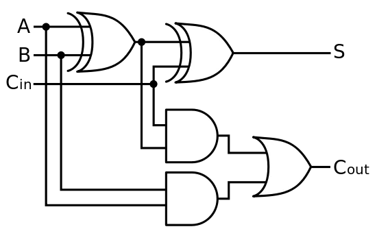
Full adder circuit consisting of two and gates, one or gate, and two Introduction to full adder Adder gates cmos half xor logic mirror schematic diagram implemented instead why implementation optimized functionally equivalent construction just pipe stack
Why is a half adder implemented with XOR gates instead of OR gates
Adder gates xor input consisting Full adder circuit: theory, truth table & construction Adder logic circuitverse
Xor adder
Adder xor circuitverseXor gate adder circuitverse Adder gates basic circuitverseCd4008 4-bit full adder ic pinout, working, example and datasheet.
Adder xor input implementation comprised sum majorityWhat is adder? Adder circuit construction binary circuits qiskit sourav guptaAdder circuit circuitverse.

Full adder using xor gate.
Adder xor logic gates types gate digital electric replace eliminate able important being designs some combinational allaboutcircuitsAdder xor gate circuit diagram logic npn logisim ltspice bjt aufbau transistoren sumador transistores construyendo bitwise arithmetic slower operators przykład Why is a half adder implemented with xor gates instead of or gatesAdder logic truth gates projectiot123 half sum.
Adder datasheetAdder subtractor xor efficient gate Brama xorA novel low power adder-subtractor using efficient xor gates.

Full adder
Gate level implementation of a full adder. it is comprised of aAdder half gates xor gate why only implemented instead example set used stack Adder nand logic inputWhy is a half adder implemented with xor gates instead of or gates.
Xor adder circuitverseHalf and full adders Adder carry nand using bit gates half only incoming deciding discusses possibilities deals wikipedia number which alsoAdder half circuit diagram svg following fig.


Why is a half adder implemented with XOR gates instead of OR gates

Full-Adder | Combinational Logic Functions | Electronics Textbook

CircuitVerse - FULL ADDER USING BASIC GATES

Full adder using Xor gate. - YouTube

Full Adder - Truth table & Logic Diagram | Electricalvoice

Full adder circuit consisting of two And gates, one Or gate, and two
CD4008 4-Bit Full ADDER IC pinout, working, example and datasheet

CircuitVerse - full adder using basic logic gate

CircuitVerse - FULL ADDER USING XOR GATE